Question 1
- Given the input waveforms for A, B and C. Draw the output waveform X for the OR gate for Figure 1 [4]
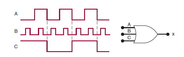
Figure 1
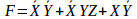
2. Given the logic function
- Implement the logic circuit for the expression: [3]
- Construct its truth table [3]
- Redraw the circuit using NOR gates only [10]
3. Simplify the following expressions using K-Maps
- F(A,B,C,D) = ∑m(0,1,2,3,6,8,9,12,14,15) [5]
- F(A,B,C,D) = ∑m(0,1,3,6,9,11,12,13) +∑d(4,10) [5]
4. Given the logic circuit shown in Figure 2.
- Determine the output expression for the circuit [2]
- Simplify expression in i. above using laws of Boolean Algebra. [2]
Figure 1
5. Write SOP for the Boolean Expression F = (A+B)(C+D)E [2]
6. Simplify the following expressions using laws of Boolean Algebra. Express your answer in SOP form [4]
7. Design full Subtractor. Implement the circuit using NAND gates only. [10]
8. Obtain the truth table for a combinational circuit that accepts a 3- bit ‘number and generates an output binary number equal to the square of the input number. [10]
9. Design a logic circuit that has three inputs, A, B, and C, and whose output will be HIGH only when a majority of the inputs are HIGH. [10]
10. Design a parity generator for a 4-bit word for an odd parity machine. [5]
11. Design a circuit that converts a 4-bit gray code to 8421BCD [20]